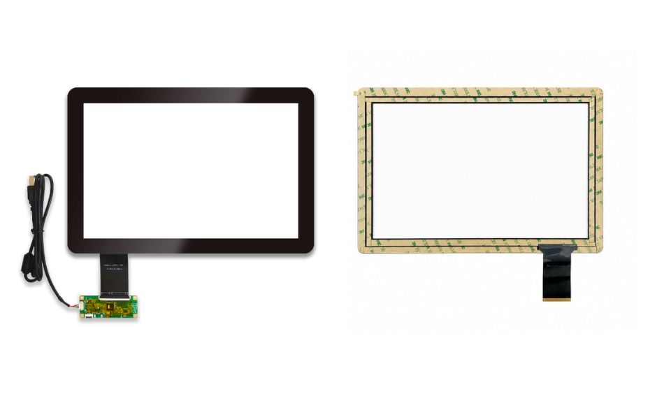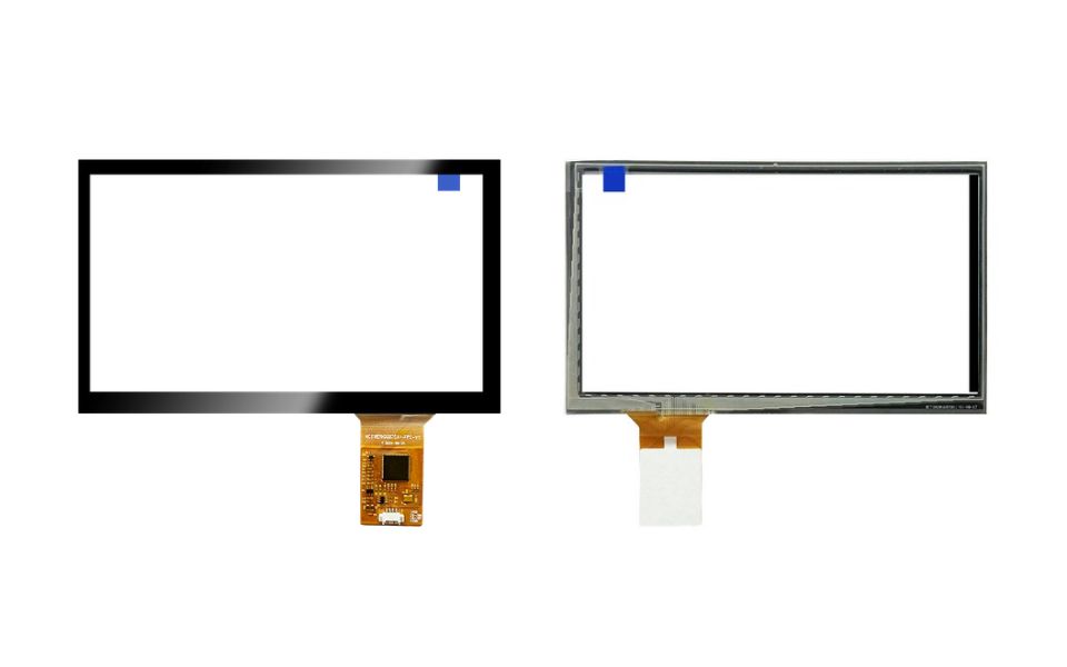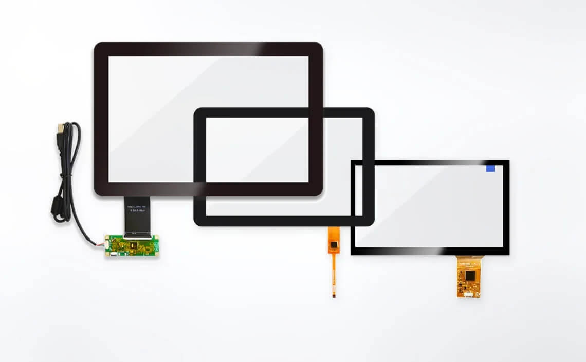
- 4 inch capacitive touch panel HCT1052GG104A1-V0 features Glass-Glass (G+G) construction with 1.80 mm AGC cover glass, 1.10 mm glass sensor and USB touch controller. Designed for standalone touch integration, this 10.4 inch touch panel offers ≥85% light transmittance, ≥6H surface hardness and black border printing. USB connectivity supports integration with compatible industrial control systems and embedded equipment. Cover dimensions, viewing area and FPC layout provide defined mechanical references for installation alongside separately selected LCD modules.
Explore More Features of 10.4 inch Capacitive Touch Panel
Glass-based touch construction, defined USB connectivity and mechanical integration features for industrial equipment.

AGC Glass & G+G Structure
G+G construction combines 1.80 mm AGC cover glass with 1.10 mm low-resistance glass sensor through 0.20 mm SCA bonding. Cover surface delivers ≥6H hardness, while light transmittance reaches ≥85%. Black border printing supports clean integration with equipment bezels and enclosures.
USB Touch Controller Integration
Integrated controller configuration supports USB touch communication through four defined signals: +5V, D−, D+ and GND. Touch sensor design specifies TX22×RX30 channels. Host compatibility, driver requirements and touch-point functionality should be verified during system integration.

Mechanical Fit & FPC Layout
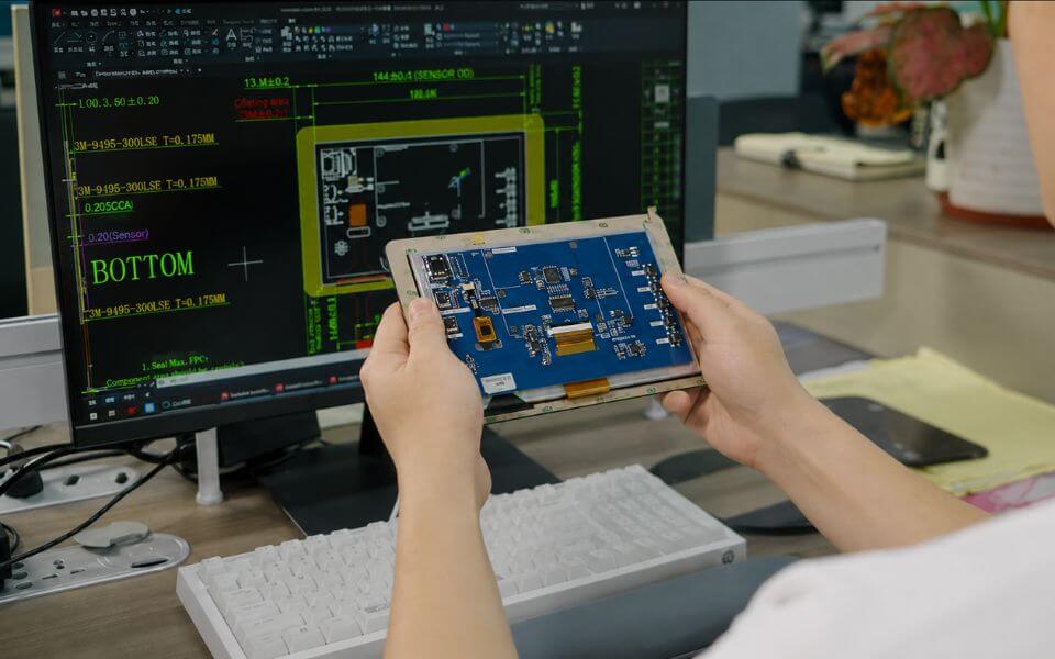
Cover lens measures 223.51×173.15 mm, with 211.60×159.20 mm viewing area. Defined FPC routing and connector-board layout support mechanical integration planning. Drawing also identifies double-sided EMI material near FPC connection area, subject to assembly-level verification.
Technical Specifications
USB Touch Panel Pin Definition
| Pin No. | Signal | Description |
|---|---|---|
| 1 | +5V | 5V power input |
| 2 | D- | USB differential data negative |
| 3 | D+ | USB differential data positive |
| 4 | GND | Ground |
FAQs
Q
1. Is the USB touch interface compatible with different operating systems?
▼
1. Is the USB touch interface compatible with different operating systems?
USB interface provides +5V, D−, D+ and GND connections. Operating system compatibility depends on touch controller firmware and available driver support. Host-system testing is recommended before production integration.
Q
2. Which operating systems support the USB touch interface?
▼
2. Which operating systems support the USB touch interface?
USB touch compatibility depends on controller firmware, operating system and driver support. Customers should provide host hardware details and OS version for compatibility evaluation. Sample testing on target equipment is recommended before production approval.
Q
3. What mounting and bonding options are available?
▼
3. What mounting and bonding options are available?
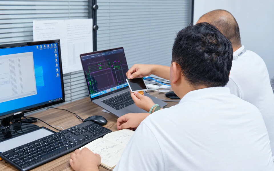
Standalone touch panels can be evaluated for frame bonding or optical bonding with compatible LCD modules. Suitable assembly methods depend on mechanical structure, available bonding space and application conditions. MAXEN can review mounting requirements and recommend appropriate integration methods.
Q
4. Which components can be customized for OEM projects?
▼
4. Which components can be customized for OEM projects?
Customization options include cover glass dimensions, border printing, FPC routing, connector position and selected surface treatments. Changes to sensor structure or controller configuration require additional engineering review. Tooling requirements, feasibility and development costs are confirmed before sampling.
Q
5. How is touch performance verified under industrial operating conditions?
▼
5. How is touch performance verified under industrial operating conditions?
Touch performance should be evaluated under actual operating conditions, including temperature changes, electrical interference and intended input methods. Glove operation, moisture tolerance and multi-touch functionality require configuration-specific validation. MAXEN recommends testing samples with final host hardware and enclosure design.